Graphite Sintering Molds Made to Your Drawing
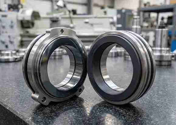
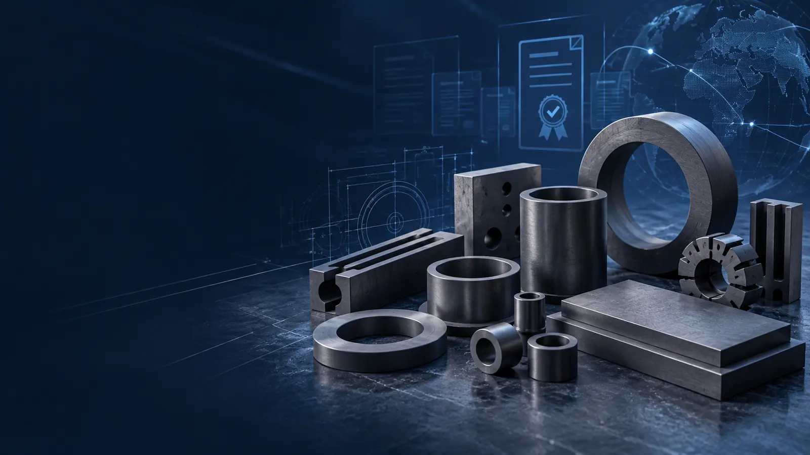
CARBOLVE machines graphite sintering mold bodies, split mold sections, punches and inserts to customer drawings. We review cavity geometry, mating features, material requirements and inspection criteria for new tooling and replacement components.
Choose the Mold Construction Around the Part
Start with the cavity, loading arrangement and removal method. One-piece bodies, split bodies and individual tooling components address different manufacturing and maintenance needs.

One-Piece Graphite Sintering Mold Bodies
A continuous graphite body containing the specified cavity geometry. Single- and multi-cavity layouts are evaluated against the drawing, with attention to wall sections, cavity spacing and the intended loading and removal arrangement.
- Cavity profile and wall sections
- Part removal and mating components
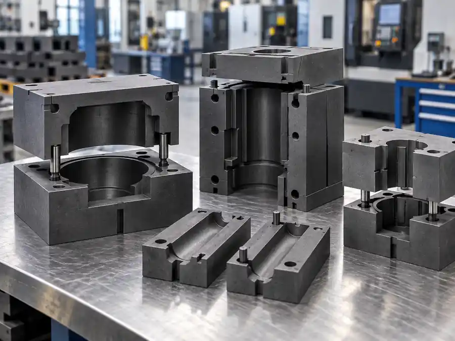
Split Graphite Sintering Mold Bodies
A cavity formed by separable graphite sections. This construction can provide access for part removal or complex profiles, while adding joint faces and locating features that must remain correctly aligned in the assembly.
- Split-line position and locating features
- Joint fit and loading arrangement
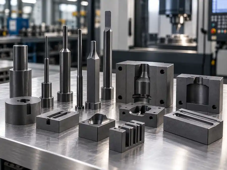
Graphite Punches & Mold Inserts
Drawing-defined components that work with the mold body. Punches transfer the applied load in pressure-assisted tooling; inserts provide specified local cavity or contact features. Replacement parts are reviewed against their mating components.
- Contact profiles and mating dimensions
- Alignment, clearances and material requirements
Separate Mold Accuracy from Sintered-Part Accuracy
The machined cavity is one part of the dimensional result. Powder behavior, compaction, thermal expansion, densification and cooling also influence the finished part. The mold drawing should incorporate the allowances established for the intended process.
Material Strength Is Not a Tool Pressure Rating
A graphite compressive-strength value is not the allowable working pressure of a finished mold. Tool geometry, temperature, loading direction, restraint and the complete assembly must also be evaluated.
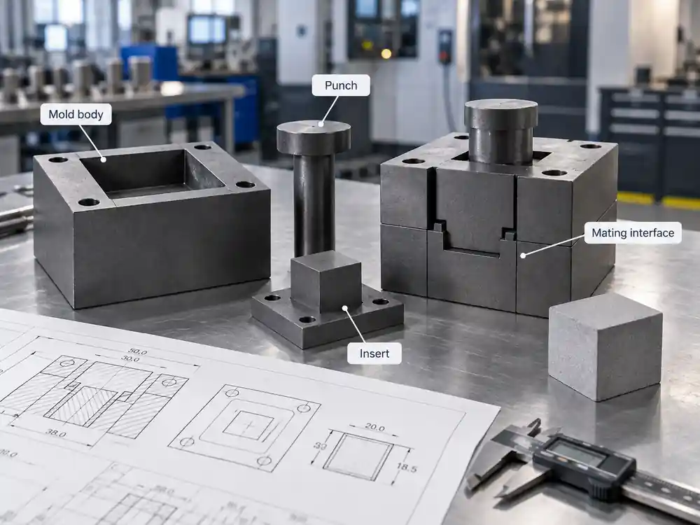
Simplified tooling relationship. Components and load paths vary by design.
| Design consideration | Why it matters | Basis for the machining review |
|---|---|---|
| Cavity dimensions and process allowance | The finished sintered part may not reproduce the room-temperature cavity dimensions. | Use an approved mold drawing that distinguishes tooling dimensions from finished-part requirements. |
| Wall sections and transitions | The mold geometry influences how loads and thermal stresses are distributed. | Review wall sections, changes in profile and the stated loading conditions together. |
| Punch-to-body fit | Alignment and clearance influence movement, contact and load transfer. | Define mating dimensions, reference datums and the conditions under which fit is evaluated. |
| Split faces and locating features | Additional interfaces create alignment and assembly requirements. | Specify joint geometry, locating details and the intended assembly arrangement. |
| Cavity surfaces and edges | Machining texture and edge damage can affect contact with the powder or compact. | Agree surface and edge requirements separately from dimensional tolerances. |
Match the Graphite to the Cavity and the Process
Material selection starts with the mold’s function. Grain structure and machinability matter for cavity detail, while mechanical, thermal, electrical and chemical requirements determine whether that material direction fits the process.
The following CVG references support preliminary discussion. Final specifications and application suitability are agreed for the individual project.
| Tooling requirement | Preliminary material references | Selection focus |
|---|---|---|
| General drawing-based mold bodies and components | CVG-ISO20 / CVG-MD30 | Geometry, material properties and operating conditions considered together. |
| Detailed cavities and precision mold features | CVG-ISO30 / CVG-FG30 | Detail retention, surface requirements and mechanical suitability—not grain size alone. |
| Fine-feature molded graphite components | CVG-MD35 | Feature dimensions, machining requirements and the conditions at the contact surface. |
| Larger mold bodies with less intricate geometry | CVG-EX40 / CVG-MD30 | Blank availability, directional properties where relevant, section geometry and loading. |
Fine Grain Helps Machining Detail—It Does Not Validate the Process
Fine-grain graphite can support smaller features and a more refined machined surface. It does not automatically provide longer mold life, greater allowable pressure or better sintered-part properties. Feature size, material behavior and process conditions still need to be considered together.
Operating Conditions Matter
Temperature alone is not enough to select a grade. Atmosphere, exposure time, thermal cycling, applied load and contact with the powder system also matter. Where current passes through the tooling, electrical properties and contact conditions become additional selection factors.
Address the Details That Can Disrupt a Tooling Order
1 A Sample Does Not Always Preserve the Original Geometry
Wear, chipping or adhered process material can obscure the original cavity and contact surfaces. CARBOLVE reviews available drawings, samples and mating-part information before agreeing the machining geometry, rather than treating every measured surface as the intended design.
2 A Replacement Component Must Match the Assembly
A new punch or insert may need to work with an existing mold body. We review the specified interfaces and material requirements so the replacement scope addresses the mating relationship, not just the loose component’s outer dimensions.
3 “Tight Tolerance” Needs a Defined Feature and Inspection Basis
Cavity size, locating features and surface condition serve different purposes. CARBOLVE reviews the critical dimensions and inspection requirements before production, helping establish what will be checked and how acceptance will be discussed.

Drawing-Based Manufacturing for Bodies and Matching Components
A Defined Supply Scope
Order one-piece bodies, split sections, punches or inserts against the relevant drawings. The quotation can distinguish complete component requirements from individual replacement items.
Material and Geometry Reviewed Together
Material direction is considered alongside cavity detail, section geometry, mating features and operating conditions. This keeps the material discussion connected to the tool being manufactured.
Machining and Finishing Around the Drawing
CARBOLVE’s graphite component work includes drilling, slotting, grinding, surface finishing and drawing-based geometries. The applicable operations and inspection requirements are reviewed for each project.
Inspection Against the Agreed Tooling Requirements
CARBOLVE’s production review includes incoming material checks, in-process checks, surface inspection and final verification. The agreed drawing and acceptance requirements guide the checks for each order.
- Material requirements before machining.
- Specified dimensions and features during production.
- Finished surfaces, edges and visible condition.
- Identification and protective packing before shipment.
Any additional material testing, dimensional records or application-specific verification should be defined before the order is finalized. Tooling inspection and qualification of the sintering process are separate activities.
Graphite Sintering Mold Buying Guide
How should I choose a graphite grade for a specific sintering temperature?
Use the temperature together with atmosphere, exposure time, loading and powder-contact conditions. Two processes at the same setpoint can place different demands on a mold.
CARBOLVE uses the cavity and component requirements alongside the CVG material directions during preliminary review. A grade reference does not, by itself, establish a validated temperature or pressure rating for the finished tool.
When is a split mold preferable to a one-piece body?
A split body may be useful when the part geometry or removal method requires the cavity to open. A one-piece body avoids those split interfaces but must still provide a workable removal arrangement.
The decision is therefore a trade-off between access, alignment, joint behavior and loading—not a rule that one construction is always stronger or easier to use.
Can these components be specified for hot pressing or SPS/FAST?
The intended process needs to be identified during technical review. Hot pressing introduces a defined load path; SPS/FAST can also involve current flow through the tooling and its contacts. Dimensions alone do not establish suitability for either process.
CARBOLVE’s confirmed offer is drawing-based machining of the mold bodies and components shown here. Equipment fit, material acceptance and process qualification must be established for the individual design.
How can I compare mold durability between suppliers?
Compare results under equivalent conditions: powder system, tool geometry, temperature cycle, loading, atmosphere, release method and the same end-of-life criteria. A cycle count from an unrelated application is not a reliable comparison.
For replacement work, records of wear location, cracks, surface changes and dimensional drift can make the next tooling review more useful than a general request for a “longer-lasting” grade.
What should a useful quotation for custom sintering molds include?
A comparable quotation should identify:
- Drawing numbers and revisions.
- Mold bodies, split sections, punches and inserts included.
- Quantity and material requirements.
- Critical dimensions, surfaces and acceptance criteria.
- Inspection or documentation requirements.
- Packing, destination and delivery terms.
For CARBOLVE inquiries, a clear component list helps distinguish an individual replacement from a set of matching parts. Price and delivery are discussed against that defined scope.
Related Graphite Products and Capabilities
Request a Quote for Your Graphite Sintering Mold
Share the mold drawing, component list and quantity. Include the powder system, process type, operating conditions and material requirements so we can review the machining scope.
For replacement parts, identify the mating components and any wear or damage that may affect the dimensions.
Email Us
sales@carbolve.com
Call Us
+86(513)-81100106
Location
No.1,Taoyuan Road, Nantong City, Jiangsu Province, China